logo

Free Shipping Over $150.00

View Free Shipping Details

Product Search

Our office will be closed from December 23rd through December 27th to celebrate the season with our family and friends. We will return on December 30th to ship orders and provide any technical assistance. Have a wonderful and safe holiday!

Airbus H125 General Familiarization - Trans Global Training

Airbus H125 General Familiarization - Trans Global Training


$698.00
SKU 1325-TRAN-Tgray stars
Which product format is best for you?
Qty

Product Features

  • Publisher: Trans Global Training
  • Time: Self Paced +/- 40 hours

General Familiarization
Course Preview (Not Actual Course)

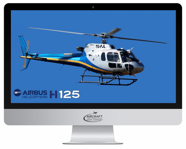
This General Familiarization course of the Airbus H125 Helicopter with Arriel 2D powerplants is designed to give you a complete technical overview of all aircraft systems as outlined in the systems description section of the aircraft maintenance manual. It is a great tool for the training of new AMTs in base and line operations, for review, and for interview preparation by those seeking employment.

This self-paced course provides a complete technical overview of each system, including component location, operation, and maintenance needs, plus all cockpit and remote interfaces. Click below on "Detailed Course Contents" for a full Table of Contents.

Upon completion of the course, you will be able to:

  • Identify safety precautions related to the airframe, its systems, and the powerplant.
  • Identify maintenance practices important to the airframe, its systems, and powerplant.
  • Define the general layout of the aircraft’s major systems.
  • Define the general layout and characteristics of the powerplant.
  • Identify special tooling and test equipment used with the aircraft.

Trans Global Training General Familiarization courses are produced for ATA 104 and EASA Part 66 Level 1+. Each is a Powerpoint type presentation divided into ATA sections. A chapter quiz following each section allows you to proceed to the next. With your successful completion of all chapters, a serial numbered certificate is issued in your name.

On average, the course duration is 40 hours, however, this will vary based on your experience and study habits. From the time you begin, you will have 1 year to complete and review the course.

Shortly after your purchase, you will receive 2 emails; The first from ATB will be your receipt. The second from Trans Global Training will be your login credentials. If these do not appear within moments of placing your order. Please check your spam files or contact us for assistance (email: techsupport@actechbooks.com or phone: 1 970 726-5111).


FAAST AMT Award Points:
This course qualifies for 40 FAA FAAST AMT Award Points, which will be issued upon your successful completion. To receive this award, you must have an account with FAAST. If you are not yet a FAAST member, your free registration can be found at https://www.faasafety.gov/login/reg/register.aspx


IA Renewal Credit
In addition, this course qualifies for 8 hours of IA Renewal Credit. If you hold Inspection Authorization (IA), this course serves as the entirety of your annual continued training requirements. Upon your successful completion, ATB will authorize this credit through the FAA and a printable IA certificate of accomplishment will be made available at https://www.FAAsafety.gov


For Training Managers:
Self paced training is a great option for your continued and recurrent needs. It is economical, efficient, and allows your team to proceed on their own or during down times, thus without the need to pull them away from the job. Contact us to discuss ways to integrate this method into your training programs.

Additional features allow for the assignment of a training manager within your company, allowing oversight of each trainee's progress throughout the course including time spent, sections completed and a record of current/incorrect quiz responses.


  • ATA 00 - Introduction
    • First contact with aircraft; Development history; Characteristics; Missions.
  • ATA 06 - ATA 12 - Helicopter Overview
    • Helicopter overview – primary dimensions of the helicopter – primary dimensions of the access items – main reference stations on the helicopter – center of gravity definition – station locations – zoning – lifting and shoring – illustration of a H125 lifting – jacking – transport – leveling – weighing – weight definition – parking – mooring – placards and markings – placards and markings example – servicing – filling and draining – fuel filling – fuel draining – main gear box filling and draining – tail gear box filling and draining – cleaning – unscheduled operation.
    ATA 21 - Environmental Control System
    • System overview – MMEL information – heating & demisting – system architecture – system components – normal functioning – induction nozzle – heating and demisting – ventilation – cockpit ventilation – cabin ventilation – scoop redesign.
    ATA 23 - Communication
    • Description and identification – purpose and characteristics – ICS identification – VHF 1 identification – VHF 2 identification – H125 – ICS GMA 350 H – GMA 350 H – basic architecture – location – PTT switches and headsets – controls and indicating – intercommunication communication – navigation – auxiliary and entertainment – blue select mode – volume – Intercommunication configuration – all mode – passenger – crew isolate mode – pilot isolate mode copilot isolate mode: copilot and passenger isolate mode – pilot and passenger isolate mode – pilot and copilot isolate mode: All isolate mode – 3D audio mode – VHF 1 system – description – basic architecture – location – GTN 650 – cyclic stick – VHF 1 antenna – COM1/NAV1pushbutton – controls and indicating - COM1 cyclic control – COM frequency selection – Find COM frequency page - COM spacing adjustment – VHF 2 system – description – basic architecture – location – GNC 255 – cyclic stick – VHF 2 antenna – controls and indicating – monitoring – COM – COM recent - emergency frequency – saving a COM frequency.
    ATA 24 - Electrical Power
    • DC power system – general description – electrical network – distribution principles – system architecture – detailed architecture – main component location – electrical master box detailed location – general controls and displays – controls and displays: VEMD – power supply from EPU – power supply from battery – power supply from generator – degraded functioning: over voltage – degraded functioning: gene reset – degraded functioning: generator return current – degraded functioning: battery temperature detection – direct battery supply – distribution – direct battery supply – contactors location – degraded functioning battery supply – breaker panel : architecture and location – limitations – electrical circuit limitations.
    ATA 25 - Equipment and Furnishings
    • System overview – seats – standard configuration – comfort configuration – emergency medical services configuration – location – front seat – location – rear seat – seats normal functioning : energy absorbing – APPAREO Vision 1000 – system architecture – main component location – main component description – camera capture example – camera monitoring – emergency locator Kannad 406 INTEGRA – ELT architecture – ELT main component location – normal functioning : in flight – normal functioning : autonomous mode – test mode.
    ATA 26 - Fire Protection
    • System overview – system architecture – component location – fire detector – current monitoring - fire detection – engine fire detection: test – cockpit extinguisher – component location.
    ATA 28 - Fuel System
    • System Overview – Architecture of the fuel system – Architecture of the fuel monitoring system – Fuel – Storage – Component Location – Component Description – Storage indication: fuel Probe – Fuel System – Distribution – General Description – Fuel System – Indicating - fuel system purge – Engine stopped – Fuel system purge – starting and fuel supply – Engine starting – Engine fuel supply in flight – Degraded functioning: Filter pre-clogging – Filter clogging – Fuel low level – Fuel low pressure.
ATA 29 – Hydraulic Power
  • System overview – location: reservoir and pump assembly – reservoir – pump assembly – location of the hydraulic control unit – location of the yaw load compensator – hydraulic filter unit: normal functioning – degraded functioning: filter clogging – hydraulic system components and their functions – operational mode and degraded functioning – system stopped – hydraulic system cut-off test – loss of the hydraulic pressure – seizure of a servo actuator distributor – yaw load compensator operation – actuator – accumulator – non return valve – solenoid valve – pressure relief valve. dual hydraulic system – introduction – architecture – location – upper hydraulic system – lower hydraulic system – tail rotor hydraulic supply line – tail rotor hydraulic actuators – control and indicating – normal functioning – degraded functioning – pressure drop in the UPPER system – pressure drop in the LOWER system – tail servo control malfunction – discharging load compensator accumulator – hydraulic filter unit – normal operation: – degraded operation: filter clogging.
ATA 30- Ice & Rain Protection
  • Introduction – pitot static system – architecture – controls and displays – location – normal functioning – windshield wiper – controls and displays – architecture.
ATA 31 - Indicating and Recording Systems
  • System overview – indicating systems – description: indicators – description: lights – architecture – location – controls and displays: caution and warning panel – controls and displays: system control unit – control panel – controls and displays: vehicle and engine multifunction display – warning information – ancillary system unit – caution and warning panel – audio alarm – test – VEMD – description – architecture – location – controls – displays – limitation displays principle – status detection – flight mode pages – info page – “vehicle/engine” page – performances – first limitation indicator – ENGINE POWER CHECK – ENGINE POWER CHECK, first page – ENGINE POWER CHECK, second page – ENGINE POWER CHECK, third page – FLIGHT REPORT – messages places – EECU messages – flight mode: degraded functioning – displays in case of failure of the VEMD’s LANE 2 – configuration mode page – maintenance mode page – pages displayed – access to the maintenance mode – flight report – failure diagnosis – complete diagnosis – parameters type 1 – parameters type 2 – parameters type 3 – over limit – engine power check – the “ENGINE POWER CHECK” page – functional times – The “FONCT.TIMES” page – EECU data – data loading.
ATA 32 - Landing Gear
  • Skid type – assembly – fittings – during flight – ground resonance – shock absorbers detailed location – operation.
ATA 33 - Lighting System
  • System overview – internal lighting – integrated lighting – architecture – location – control and display – DAY setting – NIGHT setting – “SYST. LIGHT” adjustment – “INST. LIGHT” adjustment – LED functioning – independent lighting control – VEMD brightness – automatic lighting control – DAY position – NIGHT position – external lighting – position lights - anti-collision light - taxi light – landing light.
ATA 34 - Navigation
  • Description and identification – Air data system. NAV1 identification – NAV2 identification – GPS system identification – transponder identification – helicopter’s attitude identification – horizon indicator – horizontal situation indicator – Magnetic compass identification. NAV1 presentation, overview , basic architecture, location, control and indicating – The Garmin touch navigation (GTN 650H). Navigation generalities, VOR frequency range, VOR function, ILS function , NAV function, NAV2 presentation, control and indicating, basic operation. GPS presentation, overview, basic architecture, location, control and indicating, basic operation. Transponder presentation, overview, basic architecture, location, control and indicating, basic operation. Attitude and direction presentation, overview, basic architecture. Gyro magnetic compass, gyro horizon, location, gyro magnetic compass, gyro horizon, control and indicating. Magnetic compass system, control and indicating.
ATA 52 - Doors
  • Overview – cabin doors – front doors: location – front doors: jettison system presentation – front doors: jettison system functioning – cargo hold doors – lateral cargo hold – rear cargo hold.
ATA 56 - Windows
  • Overview windows and windshields.
ATA 62 - Main Rotor Mast
  • System Overview – description – rotor mast assembly – architecture – location – detailed location. Operating principle of the NR monitoring system. Rotor speed monitoring, aural signal, continuous tone “low rotor rate” alarm, intermittent tone “high rotor rate” alarm, degraded mode, total loss of power. Main rotor hub, architecture, blade sleeve assembly. Main rotor blades, Vibration absorbers, rotor hub vibration absorber, detailed location. Resonator, general principle, resonator, vertical vibration amplitude, cabin resonators.
ATA 63 - Main Rotor Drive Train
  • System overview – Main rotor drive train. free wheel description, free wheel operating principle. Engine to MGB coupling, location. rotor brake system, location. Main gear box, location, suspension, location. Lubrication, normal functioning, degraded functioning, oil filter clogging, oil overheat, oil low pressure, oil chip detection. Indicating architecture, location, control and display, caution warning panel.
ATA 64 - Tail Rotor
  • System overview, tail rotor design principles, tail rotor characteristics, tail rotor components, location, balancing. View of the mod AMS 07 5606 and 07 6604.
ATA 65 - Tail Rotor Drive Shaft
  • System overview, tail rotor drive shafts, tail rotor transmission, detailed location, normal functioning, tail rotor drive. Detailed pictures.
ATA 64 - Helicopter Flight Controls
  • Operating principle of the flight controls; cyclic stick, roll control, lateral; collective lever, climb control, descent control; tail rotor control, pedal right action, pedal left action, action of the main rotor controls. main rotor flight control, mixing unit, collective pitch/engine governor coupling, lateral bellcrank, roll control, right movement of the cyclic stick, left movements of the cyclic stick, pitch control, forward movement of the cyclic pitch, backward movement of the cyclic pitch, descent control, pushing down the collective lever, lift control, pulling up the collective lever, mixing unit operation. components: adjustable friction mechanism, tail rotor flight control, tail rotor control pedals, tail rotor servo control, yaw anticipator. servo actuators, main rotor servo, tail rotor servo. SAMM servo actuators: general description, normal operations, neutral position, normal operation step 1, normal operation step 2, normal operation step 3, degraded operations, loss of hydraulic pressure. yaw load compensator: general overview, normal operations high pitch, low pitch.
ATA 71-80 GE CF34-3B Powerplant
  • Arriel 2d overview, characteristics, basic architecture, detailed architecture. Arriel 2d component location. Arriel 2d normal functioning; compression, combustion, expansion and transmission of the power. mounting overview. Firewalls overview, location. Engine governing system, governing architecture. Electrical power supplies. Electronic control unit. FADEC architecture. Engine governing components location, governing. Location of the EDR. Location of the temperature sensors, collective pitch anticipator, XPC, yaw anticipator. XPA – engine governing controls and indicators. engine control function . failure classification. fuel metering unit, degraded mode. EECU major failure. EBCAU overview, components location, functions, normal functioning, EBCAU test. engine indicating N2, N2a, N2b, N2c sensors location. TOT thermocouples location, normal functioning. Torque conformation. Engine data recorder overview, architecture. Lubrication system, architecture, recovery points location, oil system components location, thermostatic valve, degraded functioning, oil low pressure, chip detection. Engine starting, architecture, location. overhead panel, console, under the cabin floor, rear compartment. Starting – starting selector switched “on”, auxiliary starting relay activation, activation of the generator – twist grip to flight position. Engine shutdown. Engine cranking.

This course is an interactive General Familiarization developed by Trans Global Training. You are purchasing a license to use this course for a period of (1) one year. During this time you may use and review the course from any internet-connected device by logging in with the username and password which will be auto-generated when you complete your purchase.

Shortly after your purchase, you will receive 2 emails; The first from ATB will be your receipt. The second from Trans Global Training will be your login credentials. If these do not appear within moments of placing your order, please check your spam folder. Please keep these emails in a safe place for future reference.


Frequently Bought Together