logo

Free Shipping Over $150.00

View Free Shipping Details

Product Search
Leonardo AW139 General Familiarization - Trans Global Training

Leonardo AW139 General Familiarization - Trans Global Training


$698.00
SKU 1326-TRAN-Tgray stars
Which product format is best for you?
Qty

Product Features

  • Publisher: Trans Global Training
  • Time: Self Paced +/- 40 hours

General Familiarization
Course Preview (Not Actual Course)

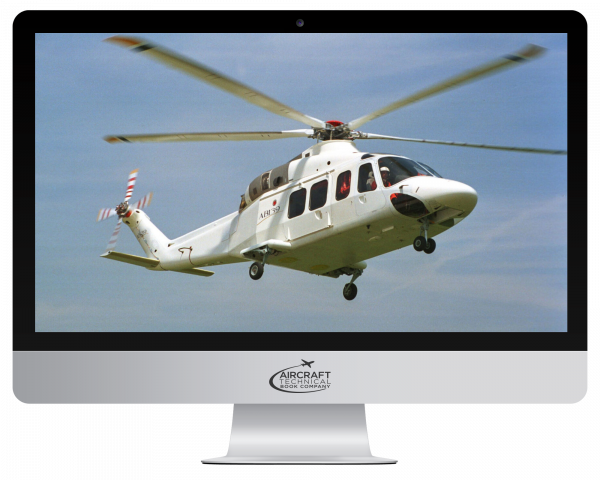
This General Familiarization course of the Leonardo AW139 with Pratt and Whitey PT6C-67C powerplants is designed to give you a complete technical overview of all aircraft systems as outlined in the systems description section of the aircraft maintenance manual. It is a great tool for the training of new AMTs in base and line operations, for review, and for interview preparation by those seeking employment.

This self-paced course provides a complete technical overview of each system, including component location, operation, and maintenance needs, plus all cockpit and remote interfaces. Click below on "Detailed Course Contents" for a full Table of Contents.

Upon completion of the course, you will be able to:

  • Identify safety precautions related to the airframe, its systems, and the powerplant.
  • Identify maintenance practices important to the airframe, its systems, and powerplant.
  • Define the general layout of the aircraft’s major systems.
  • Define the general layout and characteristics of the powerplant.
  • Identify special tooling and test equipment used with the aircraft.

Trans Global Training General Familiarization courses are produced for ATA 104 and EASA Part 66 Level 1+. Each is a Powerpoint type presentation divided into ATA sections. A chapter quiz following each section allows you to proceed to the next. With your successful completion of all chapters, a serial numbered certificate is issued in your name.

On average, the course duration is 40 hours, however, this will vary based on your experience and study habits. From the time you begin, you will have 1 year to complete and review the course.

Shortly after your purchase, you will receive 2 emails; The first from ATB will be your receipt. The second from Trans Global Training will be your login credentials. If these do not appear within moments of placing your order. Please check your spam files or contact us for assistance by email: techsupport@actechbooks.com or phone: 1 970 726-5111.


FAAST AMT Award Points:
This course qualifies for 40 FAA FAAST AMT Award Points, which will be issued upon your successful completion. To receive this award, you must have an account with FAAST. If you are not yet a FAAST member, your free registration can be found at https://www.faasafety.gov/login/reg/register.aspx


IA Renewal Credit
In addition, this course qualifies for 8 hours of IA Renewal Credit. If you hold Inspection Authorization (IA), this course serves as the entirety of your annual continued training requirements. Upon your successful completion, ATB will authorize this credit through the FAA and a printable IA certificate of accomplishment will be made available at https://www.FAAsafety.gov


For Training Managers:
Self paced training is a great option for your continued and recurrent needs. It is economical, efficient, and allows your team to proceed on their own or during down times, thus without the need to pull them away from the job. Contact us to discuss ways to integrate this method into your training programs.

Additional features allow for the assignment of a training manager within your company, allowing oversight of each trainee's progress throughout the course including time spent, sections completed and a record of current/incorrect quiz responses.


  • ATA 00 - Introduction
    • Overview: introduction to the AW139, historical background and development, market roles and applications, certification details, maximum number of occupants. Major Zones: fuselage sections, tail boom, structural components. Cockpit and Cabin: pilot and co-pilot seats, access doors and windows, passenger seats and baggage area, seating arrangements. Emergency Exits: description and operation of emergency exits. Systems Overview: power plant, engines, fire detection and extinguishing, drive system, rotors, hydraulic power, landing gear, fuel, electrical power, lighting, environmental control, avionics.
  • ATA 06 - ATA 12 - Helicopter Overview
    • Overview: principal dimensions of AW139, short nose and long nose/enhanced versions. Principal Dimensions: aw139 (short nose) dimensions, AW139 (long nose) dimensions. Reference Lines: lateral view example. Aircraft Zones: lateral view example. Access Provisions: identification code system for panels and doors, example of access door provision. Jacking: procedures and personnel required for jacking, safety precautions and steps for jacking. Slinging: procedures for slinging the aircraft, safety precautions and steps for slinging. Leveling: procedures for leveling the helicopter, purpose and equipment used for leveling. Weighing: procedures for weighing the helicopter, conditions and charts for weight calculation. Handling and Taxiing: towing procedures and precautions, taxiing requirements and procedures. Parking and Mooring: procedures for parking, mooring procedures for high wind conditions.
    ATA 21 - Environmental Control System
    • Overview: introduction to the environmental control system, sub-systems: ventilation, heating, air conditioning. Ventilation System: purpose and components, pilot and copilot ventilation, sub-systems, cabin ventilation, controls and indicators, VENT CREW rotary knob, VENT PAX rotary knob, VENT CONTR switch. Heating System: general description and purpose, components and operation, controls and indicators, COND/HTR selector, TEMP CONTR knob, SOV 1 and SOV 2 switches. Air Conditioning System: general description and purpose, components and operation, controls and indicators, COND/HTR selector, TEMP CONTR knob.
    ATA 22 - Autoflight System
    • Overview: introduction to the automatic flight control system, four configurations of AFCS. Basic Architecture: AFCS redundancy and components, autopilot modules in MAUs, MAU mounted AP/FD modules. Basic Operation: fail safe design and manual override by pilot, components and systems for dual AFCS operation. AFCS Associated Components: sensors and systems providing data for AFCS operation, AFCS indications on display units. Modular Avionics Unit: installation and functionality of AFCS modules in MAUs, redundancy and monitoring in AFCS. System Interface Components: interaction of AFCS with flight control components, linear and trim actuators. Linear Actuator: function and operation of dual linear actuators, integrity centering function and redundancy. Trim Actuator: rotary trim actuators and their components, operation and control of trim motors and force trim. AFCS – Controls and Indicators: pilot interfaces for AFCS input, autopilot controller and guidance controller functions, MISC control panel, collective lever, cyclic stick, and yaw pedals. Autopilot Indicators: PFD annunciations/displays for SAS, UCPL, and CLTV, flight director command bars and autopilot modes, MFD (AFCS synoptic page) autopilot trim position displays.
    ATA 23 - Communication
    • General Description: introduction to the communication system, main sub-systems: modular radio system and audio integrating system. System Overview: modular radio system, audio integrating system. Modular Radio System: overview, main components, modular radio cabinet (MRC), MRC modules, network interface module, radio modules (VDR, VIDL, ADF, DME, XPDR), Basic Operation, Antennas Location. Audio Integrating System: overview, main components, audio control panel, cabin audio controller, headset jack outlets, push-to-transmit switch, basic operation, audio control panel, buttons and functions, volume control, radio master system and electrical power.
    ATA 24 - Electrical Power
    • General: introduction to the 28V DC electrical power system. Main Components: starter/generator, description and functionality, maximum load versus pressure altitude, generator control unit, control, protection, and monitoring functions, batteries, types and capacities (main and auxiliary), usage and safety features, external power receptacle, functionality and safety features, power distribution panels, installation and functionality, shunts, function and placement, DC current transformers, function and safety features, circuit breaker panels, description and arrangement, electrical system control panel, switches and their functions. Indicators: voltmeter, battery amperemeters, generator load meters. Synoptic Diagram: display on the multi function , display, Information provided and caution notes. Basic Operation: description of the electrical power system subsystems, interconnection and protection features.
    ATA 25 - Equipment and Furnishings
    • Overview: introduction to the equipment/furnishings system, sub-systems: flight compartment, passenger compartment, cargo compartment, emergency equipment, cabin furnishings, insulation and lining, aerial delivery. Flight Compartment: components, cockpit seats, roof window shades. Cockpit Seats: details of seats and restraint systems, four or five-point restraint system, seat construction and energy absorption process, seat controls and fittings. Roof Window. Shades Passenger Compartment: 12 or 15 seat configuration, primary components, forward cabin seats, aft cabin seats, safety belts, headrests. Emergency Equipment: emergency locator transmitter, purpose and automatic activation, main components, ELT unit, ELT/NAV interface unit, ELT control panel, buzzer, ELT antenna. ELT System Controls and Indicators: ELT switch, ELT light, reset procedure, basic operation and transmission frequencies.
    ATA 26 - Fire Protection
    • Overview: engine fire detection system, engine fire extinguishing system, baggage compartment smoke detection. Engine Fire Detection System: components and operation, heat fire detector, firewire, responder, detailed description of components, heat fire detector composition, firewire construction and gas contents, responder’s pressure switches (high and low). Engine Fire Extinguishing System: purpose and operation, components, extinguishing bottles, double check-T valve, detailed description of components, extinguishing bottle specifications, double check-T valve functionality. Baggage Compartment Smoke Detection: components and operation, smoke detector, detailed description of components, smoke detector’s photoelectric device operation. Portable Fire Extinguishers: locations and specifications, mounting and usage, extinguishing agent, Controls and Indicators: control panel details, BAG indicator, ENG 1 and ENG 2 guarded indicators/push buttons, FIRE EXTING bottle selection switch, ARM light indications, FIRE indicators for engines.
    ATA 28 - Fuel System
    • Overview: introduction to the fuel system, sub-systems: fuel storage, fuel distribution, fuel indicating. Fuel Storage: components and operation, main fuel tanks, sump plates, water drain valves, fuel drain valve, auxiliary fuel tank, tank details, location and capacity, safety features in crash conditions. Fuel Distribution: components and operation, booster pumps, fuel manifold, fuel shut-off valves, non-return valves, cross feed valve. Fuel Indicating: components and purpose, fuel control unit, low level detection module, fuel probes, low level sensors, pressure switches, pressure transducers, fuel control panel, operation and data monitoring, fuel quantity measurement, fuel pressure indication, fuel flow data. Controls and Indicators: fuel control panel, booster pump switches, fuel indicators, cross feed valve control, fuel pressure and quantity indicators, fuel flow indicators on MFD.
ATA 29 – Hydraulic Power
  • Overview: purpose of the hydraulic power system, sub-systems: flight control circuit, utility circuit system No.1 and system No.2 details. Main Systems: hydraulic power supply to flight controls, landing gear operation in normal and emergency conditions, HYD control panel. Main Components: power control module No.1, Pump 1, electrical pump, power control module No.2, pump 2 and pump 4, tail rotor shut off valve, shut-off valve No.2. Power Control Module: main components of PCM, functionality and safety features. Indicators: synoptic diagram on multi-function display, pressure and temperature values, status indicators. Controls: hydraulic control panel functions, ELEC PUMP pushbutton, HYD 1 and HYD 2 indicators, SOV guarded switch. Basic Operation: automatic controls provided by fluid level microswitches, manual controls operated by the pilot, hydraulic system No.1 and No.2 functions.
ATA 30- Ice & Rain Protection
  • Introduction to the ice and rain protection system: pitot heating system, windshield wiper system. Pitot Heating System: purpose and operation, pitot static probe heating element, current monitor, control switch, detailed description of components, electrical heating elements, current monitoring and fail messages, controls and indicators. Windshield Protection System: sub-systems: windshield wiper systems. Windshield Wiper System: purpose and operation, arms and wiper blades, wiper motor converter, wiper control panel switches, cyclic stick momentary switches, controls and indicators, basic operation. Windshield Washer System: purpose and operation, main components, tank for washing liquid, electrical pump, sprayers on the wiper blades, controls and indicators, windshield washer push button.
ATA 31 - Indicating and Recording Systems
  • General Description: overview of the indicating/recording system, components of the system including central display system, central warning system, independent instruments, and multi-purpose flight data recorder. Central Display System: integration with primus EPIC integrated avionics system, display units and their functions. Main Components: display units, dimming control panel, cursor control devices, display controllers, remote instrument controllers, reversion control panel, Basic Operation: primary flight display, multi-function display formats, power plant, system, plan, map, composite format for single DU operation. Central Warning System: system alerts through monitor warning function software, visual indications and aural warning messages, master warning lights, master caution lights, CAS RST pushbuttons, monitor warning function software, input/output modules, aural warning generator, message priorities and formats: warning, caution, advisory, status, CAS window and message handling. Chronometers: stop watch, down counter, power sources and operation. Data Recorder. Flight Data Recorder: control unit, cockpit area microphone, accelerometer, recording and storage capabilities, underwater locator beacon. automatic start and stop of recording
ATA 32 - Landing Gear
  • Introduction to the landing gear system. Main Landing Gear: components and operation, retractable lever suspension mechanism, oleo pneumatic damping system, single tubeless wheel, shock absorber, structure and functionality, weight-on-wheel microswitch. Nose Landing Gear: components and operation, telescopic retractable type, oleopneumatic damping system, twin tube wheels, shock absorber assembly, torque link. Controls and Indicators: landing gear control lever, landing gear control panel lights, EMER DOWN push button switch. Extension/Retraction System: components and operation, landing gear control valve, extension/retraction actuators, shortening actuators, control panels and switches. Nose Wheel Steering and Center Locks: components and operation, center lock assembly, centering assembly. Wheel Brake System: components and operation, park brake control lever, reservoir, master cylinders, park brake control valve, controls and indicators.
ATA 33 - Lighting System
  • General Description: introduction to the lighting system, sub-systems: flight compartment lights, passenger compartment lights, baggage compartment lights, exterior lights, emergency lights. Flight Compartment Lighting: overview, controls and indicators, anti-storm lights, cockpit utility lights, cockpit dome light, OAT indicator light. Passenger Compartment Lighting: cabin lights, passenger reading lights, passenger warning lights. Baggage Compartment Lighting. Exterior Lighting: general description, anti-collision lights, position lights, step lights, landing lights, secondary landing light (search light), strobe lights, rotor lights, Emergency Lighting: overview, main components, controls.
ATA 34 - Navigation
  • Introduction to the navigation system integrated in the Primus avionic system. Environmental Data: air data systems, standby outside air temperature indicator. Attitude and Direction: components: attitude and heading reference systems, standby magnetic compass, electronic standby instruments. Landing and Taxiing Aids: components: radio altimeter systems, VOR/ILS/MB systems. Dependent Position Determining: components: distance measuring equipment, air traffic control transponder, automatic direction finder, global positioning system. Flight Management System: functions and components: integration of GPS, DME, VOR, AHRS, ADS. Independent Position Determining: components: weather radar system, traffic collision avoidance system. Air Data System: overview and main components: pitot static probes, air data modules, outside air temperature probes, alternate static sources. Attitude and Heading Reference System: main components: attitude and heading reference units, flux valves, AHRS control panels. Radio Altimeter: overview and main components: radio altimeter transceivers, antennas. Automatic Direction Finder: overview and main components: ADF module, ADF antenna. Air Traffic Control Transponder: overview and main components: ATC XPDR Module, top and bottom antennas. Traffic Alert and Collision Avoidance System: overview and main components: TCAS processor, configuration module, top and bottom antennas. Weather Radar System: overview and main components: receiver transmitter antenna, weather radar controller. Global Positioning System: overview and main components: GPS receiver, GPS antenna, Distance Measuring Equipment: overview and main components: DME module, DME antenna. Flight Management System: overview and main components: FMS modules, data bases.
ATA 52 - Doors
  • Types of doors: cockpit doors, cabin doors, baggage door, nose door, external power door, methods to verify door closure. Cockpit Doors: location and operation, hinges and handle mechanism, actuator for door open maintenance, microswitches for caution messages. Cabin Doors: location and operation, rails and rollers mechanism, opening from inside and outside, microswitches for caution messages. Baggage Door: location and operation, hinges and handle mechanism, microswitches for caution messages. Nose Door: operation, hinges and centering pins. External Power Door: microswitch for caution messages.
ATA 56 - Windows
  • Overview: types of windows: flight compartment windows, fuselage compartment windows, door windows. Flight Compartment Windows: left and right windshield, left and right roof window, left and right nose window. Fuselage Compartment Windows: left and right cabin windows, components and emergency removal. Door Windows: left and right cockpit doors windows, left and right cabin doors forward and aft windows, emergency removal process. Emergency Exits: location and operation, jettisonable windows.
ATA 62 - Main Rotor Mast
  • Overview: purpose of the main rotor system, components: main rotor head, blades, rotating controls. Main Rotor Head: components and operation, hub, tension links, elastomeric bearings, dampers, control levers, beanie. Blades: construction and materials, composite material, stainless steel erosion shield, fairings, mass balance weights, metallic trim tabs, lightning conductor strip, heater mat, folding mechanism. Rotating Controls & Swashplate: components and operation, pitch links, rotating scissors assemblies, adapters, swashplate assembly. NR Sensor: function and operation, interface with EEC and MAUs, backup data handling. Controls and Indicators: control components, collective grip RPM selector switch, indicator components, PFD and MFD MAIN page displays, triple tachometer scale, NF/NR indicators, primary and backup data indications, MAUs comparison function.
ATA 63 - Main Rotor Drive Train
  • Introduction to the transmission system, main components: main rotor drive system, tail rotor drive system. Main Rotor Drive System: overview and purpose, main gear box, engine gearbox couplings, input modules, freewheels. Main Gear Box: structure and function, reduction stages and output speeds, lubrication system, accessories driven by the MGB. Mounts and Attachments: support and attachment points for the MGB, anti-torque beam, rotor brake system. Engine Gearbox Couplings: function and components. Input Modules: connection and function, centrifugal freewheeling unit. Freewheels: operation and conditions, autorotation functionality. Controls and Indicators: pressure and temperature monitoring, chip burner and oil level, MGB push buttons, torque limiter switch. Lubrication System: components and function, pressure relief valves, oil filter and level sensor. Rotor Brake System: function and components, rotor brake control lever, rotor brake control module, rotor brake pressure indicator, rotor brake assembly, rotor brake actuation assembly, rotor brake relay box.
ATA 64 - Tail Rotor
  • Fully articulated rotor with elastomeric spherical bearings. Tail Rotor Head: components and operation, splined hub connecting the TGB shaft to the four blades, elastomeric bearings, elastomeric dampers, flapping movement limiters, cover. Blades: construction and materials, composite material with fiberglass tapes and layers, nickel shield for erosion protection, upper and lower fiberglass skins, mass balance pockets, lightning conductor jumper. Rotating Controls: components and operation, spider installed over a sliding tube, rotating scissors, pitch links.
ATA 65 - Tail Rotor Drive Shaft
  • Overview: Tail rotor drive shafts, intermediate gear box, tail gear box. Tail Rotor Drive Shafts: function and components, connection and torque transmission between gearboxes, shafts No.1 and No.2, and their connection to the IGB, Anti flail assembly and dampers. Intermediate Gear Box: function and components, changing drive direction and speed reduction, self contained splash lubrication and condition monitoring oil system, oil low level sensor, oil temperature sensor, accelerometer, and chip detector. Tail Gear Box: function and components, speed reduction from input to output, self contained splash lubrication and condition monitoring oil system, oil low level sensor, oil temperature sensor, accelerometer, and chip detector. Indications: display of temperature values in the IGB and TGB areas on the PWR PLANT page, green, amber, and red bands indicating normal, caution, and warning conditions. Controls and Indicators: chip burner push button, oil level IGB and TGB push buttons, Display of caution messages in the CAS window.
ATA 67 - Helicopter Flight Controls
  • Overview: purpose and components of the rotor flight controls, main rotor controls system, tail rotor controls system, rotor flight controls indicating system. Main Rotor Controls System: overview, collective control, collective trim actuator, basic operation, cyclic control, cyclic control – principle of operation, mixing unit, main rotor servo actuators. Tail Rotor Controls System: yaw control, pilot pedal assembly, copilot pedal assembly, yaw trim actuator, yaw dual linear actuator, tail rotor servo actuator – principle of operation. Controls: FORCE TRIM switch, CLTV / YAW TRIM switch, FTR push button switch, CLTV PLT, CLTV CPLT
ATA 71-80 PW PT6C-67C Powerplant
  • General description, engine installation details. Main Components: diagrams and descriptions of engine components, locations and functionalities. Engine Stations and Operating Conditions: description of engine stations, pressures and temperatures at each station. Main Engine Bearings: types and functions of main engine bearings, lubrication and vibration dampening. Engine Cases and Flanges: structural cases and their functions, disassembly locations. Engine Mounts: mounting points and their functions, thermal expansion allowances. Firewall Compartments: firewall structure and components, fire detection and extinguishing circuits. Air Inlet Case and Compressor Assembly: function and components of the air inlet case, compressor assembly and basic operation. Combustion Chamber: function and description, basic operation. Hot Section Components: functions and descriptions, basic operation. Compressor Turbine: function and components, basic operation. Exhaust Case: function and description, basic operation. Accessory Gearbox: functions and descriptions, basic operation. Engine Fuel and Control: overview and main components, basic operation. Ignition System: overview and components, operation, controls and indicators. Air System: primary and secondary air systems, basic operation. Engine Controls: normal automatic mode, manual backup mode, controls and indicators. Engine Indicating System: display of engine parameters, engine ratings and modes. Exhaust System: general description and components, function. Engine Oil System: components and functions, pressure, scavenge, and breather systems indications.
ATA 95 Emergency Floatation
  • Introduction to the emergency flotation system, activation methods: automatic and manual, system installations and structure, attachment to the helicopter frame. Primary Components: forward and aft float assemblies, bottle assembly, submersion switches, relays. Forward Left and Right Float Assembly: description and function, components: gas inlet non-return valve, inflate/deflate check valve, relief valve, connection to the helicopter structure. Aft Left and Right Float Assembly: description and function, components: gas inlet non-return valve, inflate/deflate check valve, relief valve, connection to the helicopter structure. Main Components: bottle assembly with helium, relay k41 and k42, submersion switches. Controls and Indicators: emergency flotation control panel, FLOATS EMER switch, FLOATS EMER TEST pushbutton, LH/RH bottles lights, float guard and FLOAT switch on pilot collective grips. Indicators: Conditions for #1 or #2 FLOATS ARMED caution message on MFD CAS window. Basic Operation: compatibility with 28V DC supply, automatic and manual activation, Inflation process.

This course is an interactive General Familiarization developed by Trans Global Training. You are purchasing a license to use this course for a period of (1) one year. During this time you may use and review the course from any internet-connected device by logging in with the username and password which will be auto-generated when you complete your purchase.

Shortly after your purchase, you will receive 2 emails; The first from ATB will be your receipt. The second from Trans Global Training will be your login credentials. If these do not appear within moments of placing your order, please check your spam folder. Please keep these emails in a safe place for future reference.


Frequently Bought Together